| Overview | This example is intended for users with: - GUI familiarity = medium
- ADAMS experience = low
This example presents a textbook type problem relating to a crank-slider mechanism. Hints on model creation are given but not step-by-step instructions. Model consists of three moving parts and four joints. If you have trouble creating the model, you also have the option of downloading (Shift+LMB) the command file containing the model: crank_slider.cmd |
| Example | ADAMS Labs: Crank Slider
Prerequisites:Knowledge of the following skills is necessary for the completion of this ADAMS Lab. To review these skills, please refer to ADAMS/View tutorials and documentation.
- Creating a model, setting units and gravity
- Creating parts and joints
- Running and animating a simulation
- Plotting results
Problem: Problem 2/163 from J. L. Meriam and L. G. Kraige, Engineering Mechanics: Volume 2, Dynamics 3rd edition. John Wiley & Sons, Inc. Copyright © 1992, by John Wiley & Sons, Inc.
This material is used by permission of John Wiley & Sons, Inc. | Pin A moves in a circle of 90-mm radius as crank AC revolves at a constant rate beta-dot = 60 rad/s. The slotted link rotates about point O as the rod attached to A moves in and out of the slot. For the position beta=30 degrees, determine r-dot, r-double dot, theta-dot, theta-double dot. | 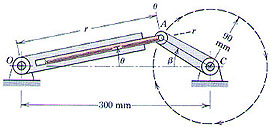 |
This problem asks for the translational speed and acceleration of the slider rod and the angular speed and acceleration of the slider assembly at a given crank angle of 30 degrees and crank angular velocity of 60 radians per second. To solve this, we will build an ADAMS model of the crank and slider assembly based on the information given and measure the data we want using an ADAMS simulation of the model.
Procedure: This ADAMS model will be created in the following steps: 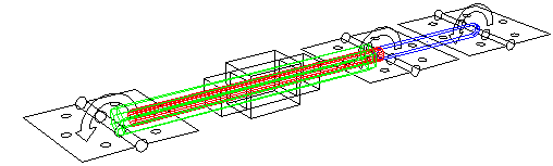
- Start ADAMS.
- Create a new model. (Units = mmks, Gravity = -y earth)
- Create crank part AC. (link, length = 90-mm)
- Create cylinder part. (revolution, length = 210 mm, outer radius = 10 mm, inner radius = 5 mm)
- Create piston part. (cylinder, length = 210 mm, radius = 5 mm)
- Create revolute joints at crank end, between crank and piston, and at cylinder end.
- Create translational joint between piston and cylinder.
- Set initial velocity of crank. (wz = -60 rad/s)
Testing the ADAMS model: - Create measures for displacement, rate, and acceleration for piston extension OA. (Build > Measures menu)
- Create measures for anglular velocity and acceleration of the slider relative to ground.
- Run analysis.
- Plot results and determine rate and acceleration of displacement r and angle theta.
Solution: r-dot = 3.58 m/s, r-double dot = 315 m/s^2, theta-dot = 17.86 rad/s, theta-double dot = -1510 rad/s^2 ADAMS simulation answers when Beta=~30deg (at t=0.008727s) were: (a) Theta = 11.46deg (b) Theta_dot = 17.86rad/s (c) Theta_double_dot = -1510rad/s^2 (d) R = 226.6m (e) R_dot = 3.575m/s (f) R_double_dot = 317m/s^2
Download the ADAMS command file for this model: crank_slider.cmd
Helpful Tips: - Make sure correct units are set to mmks.
- Make sure gravity is on and in the -y direction and set to 9806.15.
- Make sure the revolute joints are in the z direction.
- Check dimensions of the part to make sure they are correct.
- Make sure the measures are set correctly.
- Make sure the plot is displaying the correct set of results.
- Make sure there are enough output steps to observe the speed and acceleration when beta=30 deg.
Last modified 1998.09.14. |
| Files | 2163mod.gif (4377 bytes)
2163prob.jpg (14891 bytes)
2163sln.jpg (42813 bytes)
crank_slider.cmd (15402 bytes)
|
| See Also | 8703 - Index of ADAMS/View Lab examples from ADAMS installation directory.
|
| | Last modified Tuesday, September 26, 2000 at 5:13:43 PM | | Article created Saturday, July 22, 2000 at 12:07:40 PM | | Keywords: example,low,medium,kinematic,motion,simple | | Article Category: Tools |
| |
|