| Overview | This example is intended for users with: - GUI familiarity = medium
- ADAMS experience = low
This example presents a textbook type problem relating to a four-bar mechanism. The problem requires finding part angular velocites given the geometry and an input link with angular velocity. Hints on model creation are given but not step-by-step instructions. Model consists of three moving parts and one imposed motion. If you have trouble creating the model, you also have the option of downloading (Shift+LMB) the command file containing the model: fourbar.cmd |
| Example | ADAMS Labs: Four-Bar
Prerequisites:Knowledge of the following skills is necessary for the completion of this ADAMS Lab. To review these skills, please refer to ADAMS/View tutorials and documentation.
- Creating a model, setting units and gravity
- Creating parts and joints
- Running and animating a simulation
- Plotting results
Problem: Problem 5/84 from J. L. Meriam and L. G. Kraige, Engineering Mechanics: Volume 2, Dynamics 3rd edition. John Wiley & Sons, Inc. Copyright © 1992, by John Wiley & Sons, Inc.
This material is used by permission of John Wiley & Sons, Inc. | In the four-bar linkage shown, control link OA has a counterclockwise angular velocity omega = 10 rad/s during a short interval of motion. When the link CB passes the vertical position shown, point A has coordinates x = -60 mm and y = 80 mm. By means of vector algebra, determine the angular velocity of AB and BC. | 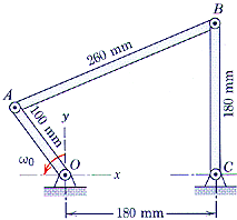 |
This problem asks for the rotational velocity of segments AB and BC when the system is in the pictured position, given a constant and known rotational velocity for segment OA. We will use ADAMS to create a model with the given conditions and collect the data needed.
Procedure: This ADAMS model will be created in the following steps: 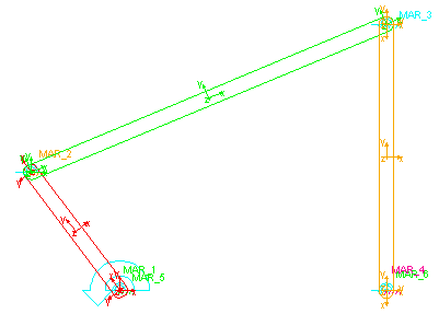
- Start ADAMS.
- Create a new model. (Units = mmks, Gravity = none)
- Create a marker at each of the following coordinates:
O (0, 0, 0); A (-60, 80, 0); B (180, 180, 0); C (180, 0, 0) - Create links OA, AB, and BC, using the markers as end points.
- Make revolute joints between two links at points A and B, and between link and ground at O and C.
- Apply motion to revolute joint connecting OA to ground with magnitude (omega_dot= 10 rad/s)
- Create Function measures for the angular velocities of the two links AB and BC relative to ground (in rad/sec).
Testing the ADAMS model. - Run simulation (end time = 1.5)
- Go to the plotting window and view plots for displacement of OA and angular velocities of AB and BC.
- Get value of angular velocities of AB and BC at t=0 (that is, when system is in the specified configuration).
Solutions: Theoretical: ADAMS at t=0.0sec: Download the ADAMS command file for this model: fourbar.cmd
Helpful Tips: - Make sure correct units are set to mmks and the viewing area is zoomed in or out enough to see the model. It may be helpful to set the working grid to 10mm spacing and change the icon size to 10mm under the Settings menu.
- Make sure the revolute joints are in the z direction.
- Check dimensions of the part to make sure they are correct.
- Make sure the measures are set correctly.
Last modified 1998.09.14. |
| Files | 584mod.gif (3926 bytes)
584prob.gif (7717 bytes)
584sln.gif (14065 bytes)
fourbar.cmd (11499 bytes)
|
| See Also | 8703 - Index of ADAMS/View Lab examples from ADAMS installation directory.
|
| | Last modified Wednesday, September 27, 2000 at 12:05:39 AM | | Article created Monday, July 24, 2000 at 8:43:42 AM | | Keywords: example,low,medium,simple,fourbar,textbook,kinematic | | Article Category: Tools |
| |
|